
Agile Requirements Modeling: An Example
- The focus of this article is requirements modeling. Whenever the discussion strays into territory that pertains to another type of modeling – analysis, architecture, or design – I’ll stop the discussion. Agile software development is highly iterative, and as a result the lines between requirements and other forms of modeling quickly become blurred in practice.
- This is one of many ways that you could take and still be considered agile. Remember, AM is a practices-based methodology, it does not define a specific, prescriptive way to work and therefore there are many ways to apply it appropriately. Don’t worry, I’ll point out other alternatives that I may have chosen at various points but please keep an open mind.
- The SWA Online team is following an Agile UP process, therefore artifacts such as use cases will play an important role in the requirements modeling process. Had they taken more of an eXtreme Programming (XP) approach user stories would instead dominate. See the AM and XP where I discuss this case study from an XP point of view.
- As I wrote this article I found it much easier to discuss my approach as if it had actually happened even though the case study is fictitious and merely based on my experiences at real organizations building e-commerce systems.
- It is best to think about requirements modeling from two different points of view: initial modeling and detailed model storming.
1. Initial Envisionment
Initial requirements modeling occurs at the beginning of the lifecycle of your initiative, in the case of the Agile UP during the Inception phase and The Eclipse Way during the Warm-Up iteration. With an Agile Model Driven Development (AMDD) approach this occurs during “iteration 0”. During this effort there are three main goals:
- To identify the scope, at least at a high level, of the system that you are building so as to define the boundary of your efforts.
- To define the high-level requirements for your system.
- To build a consensus amongst your stakeholders and within your development team as to what the requirements imply.
The initial requirements envisionment effort can be as short as a few hours, particularly if you are co-located with your stakeholders and they are able to come to a general consensus as to what the system should do, or could stretch on for several days or even weeks in situations that are less than ideal (see Overcoming Common Requirements Challenges ). You will typically hold large modeling sessions, which typically:
- Are long, sometimes several days in length for large efforts
- Have many stakeholders involved so as to hear the requirements from a wide range of people
- Tend towards the formal end of the scale (often due to the larger number of people and sometimes due to a lack of familiarity of your stakeholders with more agile approaches)
- Include some developers, particularly when you want to start building an understanding within your team of what the system is to accomplish
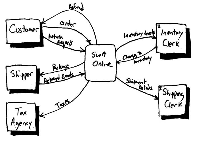
The scope of your system may be defined by a single statement, in the case of SWA Online it may be something as simple as “To sell our products to customers via the Internet” or a statement with greater detail such as “To sell physical, but not virtual, products to existing or new customers in the Continental United States”. Your system scope may also be defined using a context model – a model showing how your system fits into its overall environment – something that is often depicted using a use case diagram, as you see in Figure 2, or as a dataflow diagram (DFD) as in Figure 1 (this style of diagram is often called a “level-0” DFD). It is important to understand the scope of your system so as to limit your development efforts. The first statement was too vague, it could be taken to mean that you are selling to international customers, a significantly greater effort than selling only within the USA, as well as selling virtual products such as online music which would require the addition of an online delivery system as well as a physical one. You may find that your scope changes over time, a decision to be made by your stakeholders, so be prepared to embrace change.
Figure 1. A data flow diagram (DFD) used to model the context of SWA Online.

Figure 2. A use case diagram used to model the context of SWA Online.

So which is the best artifact to describe the scope of your system? A statement, a DFD, or a use case diagram? Depends on your situation. Statements are straightforward but often not as communicative as a diagram. The DFD of Figure 1 shows the system in the center of the diagram and its relationships with other external entities – organizations, people, or other systems – that are outside the scope of your control yet still interact with your system. A major advantage of this approach is that it depicts in reasonable detail the major flow of information between your system and the outside world. The use case diagram of Figure 2 takes a different tack, depicting the system in the center once again and the actors (organizations, people) that interact with your system. The main advantage of this approach is that it depicts both the external and internal actors that interact with your system, as opposed to the DFD that just depicts the external ones. The main disadvantage is that it does not indicate any details regarding the interactions between the system and the actors. Which diagram should you create? Both have their advantages and disadvantages, so perhaps you should consider creating both? Hmmmm”¦ doesn’t sound very agile to me. A better approach would be to create one diagram, breaking the rules a bit and combining the best of both diagrams in one as I’ve done in Figure 3. Notice how I’ve indicated the internal entities with an “I” in the top corner of the two entities, my own style, and dropped the numeric identifiers with the entities: id numbers are difficult to maintain manually and I’d rather have a rule that entity names are unique and thus they can take on the role of the identifier if needed. I could just as easily used use case notation, although had I chosen to show data flow I would have broken a serious use case modeling rule, but luckily my stakeholders liked DFDs so I went with their preference. Remember that the principle Model With a Purpose recommends that you know your audience, enabling you to pick the artifacts best suited to them.
Don’t be afraid to break the rules. Although general practice is to not include internal entities on a level-0 DFD, the idea is that you introduce internal entities when you start digging into the details, I’ve chosen to do so anyway in Figure 3 because it enabled me to avoid drawing a second diagram. The important thing to notice is that the world hasn’t come to an end and the modeling police haven’t charged me with software process malpractice. Yes, I have arguably gone against the practice Apply Modeling Standards, but in doing so I have reduced both development and maintenance costs, which indicates to me that my organization may want to rethink this standard if it becomes a huge issue for someone.
Figure 3. A DFD including internal entities to model the context of SWA Online.
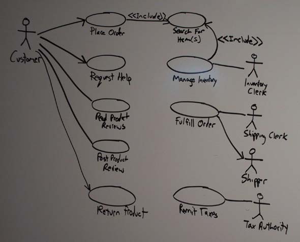
The use cases would be described simply, during your initial modeling efforts a point-form description of the logic for each use case may be sufficient. You don’t need to specify the system in detail at this point, you only need to gain a basic understanding of what the system should accomplish and to identify the initial scope for the system, and a point-form description of each use case and actor does this. If your stakeholders allow it you may not even need to go this far – perhaps identifying three or four use cases is enough for now. If it is then apply the principle Model With A Purpose and stop your initial requirements modeling efforts for now, moving on to detailed modeling efforts that drill down into the modeling and implementing the requirements you have already identified.In Figure 4 you see that I have applied the UML stereotype <> on a requirements diagram, yet in The Object Primer 3/e I recommend that you apply stereotypes on analysis-level use case diagrams, typically referred to as system use case diagrams because they often reflect architecture and design issues, but not requirements-level use case diagrams. Once again the world hasn’t ended and the modeling police haven’t charged me with crimes against software development humanity. The diagram is interesting because it shows that it is common for models to cross process boundaries, in this case the diagram reflects what I would consider to be both requirements and analysis issues.It’s easy to say that you need to reach a common consensus between stakeholders but much more difficult to achieve it in practice, even if you have overcome the common challenges to requirements efforts. Individual stakeholders have different backgrounds, different priorities, and different preferences. To build a consensus everyone needs to recognize this fact, communicate what they need from the system, listen to what others have to say, and be prepared to work towards a common goal. Whenever I’m working with a group that is having a problem coming to consensus we’ll write down everyone’s issues on a plain old whiteboard (POW) where everyone in the room can see and discuss them – this visually depicts the extent of the group’s differences and provides a focus for their discussion. Sometimes we’ll remove an issue from the board, or better yet simply cross it out because I often want to record scoping decisions (more on this soon), after the originator of the issue recognized that it wasn’t required or at least wasn’t important as other issues. I also like to draw lines between contradictory issues so as to highlight the need to discuss them, often using a specific color of marker for just that purpose.As the group focuses on high-level usage requirements they will often identify related business rules and constraints, as well as technical requirements and requirements that the system may or may not need to fulfill at some point in the future. During initial modeling you should prefer “park” business rules, constraints, and technical requirements, often writing them on flip chart paper or on the POW, capturing just enough information so that you know what the requirement is when you explore it in greater detail later. The goal is to get out of initial modeling as quickly as possible so you want to avoid investing time exploring details – when you start to explore details in these initial requirement sessions you put your team at risk because you are not obtaining concrete feedback regarding your work and of suffering from analysis paralysis. Remember the principle Software Is Your Primary Goal and not to produce models and documents describing what your software is supposed to do. For example, as in the initial requirements modeling session for SWA Online my stakeholders identified several business rules and constraints pertaining to fulfillment of orders, such as how to pack certain types of goods, how some products have finite shelf lives, and the pick-up procedures of our shippers. Whenever I hear requirement such as this I ask someone to write it down, either on the POW or on an index card that is then placed on a shared desk where everyone can see it.
This leads to an important point: modeling sessions are interactive. Everyone participates. At the start an experienced modeler will need to start the effort, explaining the techniques and prodding people to pitch in. This prodding may be something as simple as asking someone to come to the POW and explaining what they’re talking about, filling out an index card to summarize a business rule, or writing on a Post It note to record a data requirement for a potential report. As people become accustomed to these sorts of modeling activities, in accordance to AM’s Active Stakeholder Participation practice, you will find that you need to do less prodding to get them to participate. Yes, some people are shy at first and may need more prodding than others but that’s human nature (given the choice, I prefer to have very outgoing stakeholders involved with development efforts as opposed to shy ones that don’t speak their minds).
As your team identifies requirements for the current release that you are working on they will often identify requirements for future releases, or potential requirements that you may need to implement at some point. You don’t want to lose this information, although at the same time you don’t want to invest too much time exploring it nor do you want to invest any time overbuilding your software to fulfill these potential requirements. However, there is some value to your architectural efforts – potential requirements may provide insights into the merits of one architectural alternative over another. Change cases are a simple technique for documenting potential requirements, as you can see in Figure 5 which depicts two change cases for SWA Online. An important part of your scoping effort is to identify both what is currently in scope and what is currently out of scope, and by identifying a requirement as a change case you are explicitly stating that it is currently out of scope. The effective use of change cases as architectural requirements is described in detail in the Agile Architecture article.
Figure 5. Two change cases for SWA Online.
| Change: Expansion into North America
Likelihood: Very Likely Timeframe: 12-18 Months Impact:
Change: Sale of Virtual Products (online music, video, books, “¦) Likelihood: Very likely Timeframe: 6-12 months Impact:
|
So how much documentation should you write to record your understanding of the initiative’s scope and initial, high-level requirements? As I suggest in Agile Documentation, just barely enough. In the case of SWA Online we would likely create an HTML page with the context diagram of Figure 3, the use case diagram of Figure 4, and a point form list indicating what is in and out of scope. To create the high-level requirements document I would be tempted to have the use case descriptions transcribed into individual word processing documents, or perhaps even simple text files, because we’ll want to evolve them as part of our detailed modeling efforts. Having them as electronic files makes them easy to share and manipulate. As far as the index cards that we created – the placeholders for business rules, constraints, technical requirements, and change cases – I would ask my stakeholders to trust me and to leave them as is because this items will be evolved during detailed modeling efforts, if we find that we need them at all, and we can deal with them as we need to at that point. This enables the team to quickly get into detailed modeling efforts, and then into implementation, because they have avoided documentation efforts that they may not even need (some of those business rules may prove inconsequential and therefore any effort invested in documenting them before you know their true value would be a waste).
2. Detailed Requirements Model Storming
Once the scope and high-level requirements for your system have been agreed to, the result of your initial modeling efforts, you are in a position to define a schedule for your development efforts where you schedule the requirements into iterations. With this plan in place, a plan that evolves over time as your understanding of the requirements evolves, you are now in a position to start actual development.
2.1 Starting an Iteration
At the beginning of an iteration the various requirements will be spread amongst the developers. On an Agile team people volunteer to work, in pairs, on a given use case (or portion thereof), repeating the process of signing up for new use cases throughout the iteration until none are left. The first step is to understand what your stakeholders want, in detail, which will likely entail some requirements modeling.
There are two basic approaches to modeling that development teams will take at the beginning of an iteration:
- Group modeling of all the requirements for that iteration. With this approach the entire team, including available stakeholders, work together to explore the detailed requirements, to analyze those requirements, and to propose changes to the existing system design to support those requirements. Assuming your iteration is two-weeks long, my expectation would be that this modeling session would last from anywhere between one hour and a half day – if your iteration is longer, say between four and six weeks, you may decide to invest an entire day in this initial effort. You don’t want to go any longer than a day with this effort because you are not receiving the concrete feedback that you get when you Prove It With Code. The strengths of this approach is that it builds a concrete vision of what the team is working on for that iteration and how they intend to approach their work and it garners the input of all team members and therefore increases the chance of identifying a good initial approach. The weaknesses of this approach is that it only works for small teams, typically of less than ten people, and it wastes time on an individual basis because not everyone will participate on every aspect of the modeling effort. Note that once the initial modeling effort is performed for the iteration that the individual subteams will still need to model the specific details of what they are working on at appropriate times throughout the iteration.
- Individual subteams model their requirement(s). Some development teams will choose to forgo a group modeling effort at the beginning of an iteration and simply let the individual subteams dive right into implementation (see below). This works well when the requirements are not related to one another, or at least not too much, and when developers are following the practice Collective Ownership and working from a shared code base. The advantage of this approach is that it enables your team to get right into the details on the very first day of the iteration. However, there are several disadvantages. First, when the requirements overlap within sections of your design, perhaps two subteams are working on something related to calculating the total of an order (e.g. calculation of taxes by one team and calculation of discounts by another team), then you run the risk of the two subteams doing overlapping work. This shouldn’t be a serious problem because each subteam should know what the others are doing and should therefore work together as needed. Second, it takes longer for your team to gel its implementation vision for the current iteration. Third, you may initially have contention for access to stakeholders because the individual subteams all need input to get started.
2.2 During An Iteration
Once you’ve gotten over the initial kick-off efforts for an iteration your team quickly falls into a constant effort of model storming, coding, testing, building, and potentially deploying your software. It is during this period that the majority of your requirements modeling efforts with your stakeholders will occur, the goal being to explore their requirements in detail. Actually, it is more accurate to refer to these efforts simply as modeling sessions because you will very likely iterate through requirements, analysis, and design. These sessions are typically performed in an impromptu fashion by small groups of people, typically a development subteam working on a requirement and one or more stakeholders providing input. Impromptu modeling sessions are typically sort and often initiated along the lines of a question such as “Sally, do you have a couple of minutes to explain how customers search for an order item?”
So how would I approach detailed requirements modeling for SWA Online? First, let’s assume that the two of us are working together as a pair and that our team will be implementing the order definition and placement portions of the basic course of action for the “Place Order” use case in this iteration. We won’t be implementing search functionality, any sort of error or exception handling, tax calculations, or discount calculations right now. This example reveals a common problem with use cases – they are often too coarse-grained to schedule into a single iteration. You are often motivated to either schedule a single use case across multiple iterations, something that is uncomfortable from a project management point of view, or refactor your use case into a collection of smaller ones which is often uncomfortable from a modeling point of view.
The basic course of action is often called the “happy path” because everything works in the basic course of action – the alternate courses of action describe when things don’t work well, in the case of placing an order this would include being out of stock of an item that the customer has requested. However, our goal this iteration is to focus simply on a portion of the happy path for now, the other requirements will be worked on either by other subteams or perhaps by us at a later date.
The first thing that we do is flesh out the logic for the basic course of action, which is presented in Figure 6, and in parallel work on essential (abstract) UI prototypes relevant to this use case. We work on these two artifacts in parallel because they each approach the problem from a different direction, the use case describes what the customer does to place an order and the essential UI prototype specifies what the user interface of SWA Online must include to support this behavior. Notice how the use case invokes the “Search for Item(s)” use case on line two, consistent with the application of the <> stereotype in Figure 4. Even though this functionality is invoked in the part of the use case that we’re currently focused on we won’t be implementing that functionality yet because it’s not in scope. Instead we’ll stub out what we need, perhaps going straight to a results page listing the theoretical results of our search. Later on in the initiative the searching functionality will be added as appropriate, just not now (remember, we’re working incrementally). Also notice how the use case doesn’t take into consideration any sort of technology issues yet, issues that we may decide to address later. Right now we just want to understand the basic process of placing an order, we can worry about implementation details later (potentially in a few minutes from now). The use case describes logic that we won’t be implementing this iteration, such as the calculation of taxes and discounts, functionality that we’ll need to stub out when we’re coding.
Figure 6. The basic course of action for placing an order.
| 1. The use case begins when a customer chooses to place an order.
2. The customer searches for items via the use case “Search for Item(s)” 3. The customer selects adds an order item to their order. 4. The customer indicates the number of a given item they wish to order. 5. The system calculates the subtotal for the item by multiplying the unit price by the number ordered. 6. The customer repeats steps 2 through 5 as necessary to build their order. 7. The customer finishes adding items to their order. 8. The customer provides their ship to and bill to information, including their name, phone number, and surface address. 9. The system calculates the subtotal for the entire order by adding the subtotals of the individual line items. 10. The system calculates the taxes applicable for the order according to the business rule Calculate Taxes for an Order. 11. The system calculates applicable discounts for the order according to the business rule Calculate Discounts for an Order. 12. The system displays the applicable taxes and discounts. 13. The system calculates the grand total for the order by adding the applicable taxes to the order subtotal and subtracting the discounts. 14. The system displays a summary of the order. 15. The customer verifies that the order is what they want. 16. The system schedules the order for fulfillment (see the use case Fulfill Order). 17. The system produces a receipt for the customer summarizing the order.
|
Although we know that we’ll be implementing the UI in a browser we still choose to work with Post It notes and flip chart paper, instead of an HTML editor, because the paper is more flexible and flexibility is what we need right now – as we initially explore the requirements we will be adding UI elements, moving them around, and moving them very quickly and we want to use a tool that supports this effort. Later on, once the requirements for the page(s) have stabilized we’ll switch over to an HTML editor because we’ll want to make our UI more concrete for our stakeholders to evaluate. For now we keep it simple.
We are following several of AM’s practices during this effort. We are clearly following the practice Create Several Models in Parallel< /a>because we are working on a use case and essential UI prototype, and Model With Others because the team is currently comprised of the two of us and as least one stakeholder that is providing requirements. We are also following the practice Depict Models Simply. I would also argue that Figure 6 is a good example of an application of the practice Create Simple Content because it provides just enough details to describe the business logic of the use case. We are also following Apply The Right Artifact(s) – business rules are being captured outside of the use case, although you could argue that the logic for calculating the grand total of an order is a simple business rule, in a separate business rules artifact (for now you would want to create placeholders for Calculate Taxes for an Order and Calculate Discounts for an Order, either sections in a word processing document or as individual index cards). Furthermore user interface requirements are being captured in a separate artifact, the essential UI prototype, and if we felt the need “data requirements” could be captured in a conceptual model (more on this below). We also followed the practice Iterate To Another Artifact, moving back and forth between working on the use case and the essential UI prototype – as we added features to the UI prototype we realized we were missing logic in the use case and vice versa. Finally, we applied the practice Use The Simplest Tools – the UI prototyping was done using paper and the use case logic was written on a POW.
Assuming that we were satisfied with our modeling efforts, more than likely an effort that took between thirty and sixty minutes, we would either continue on through analysis and design and finally into implementation or we would first invest a few minutes to update the team’s domain model with what we have just learned. I prefer to keep domain models as simple as possible, using CRC cards perhaps, because they are easy to work with and very accessible to stakeholders. Not only can they be used to show the major entities within your domain but their responsibilities as well, including both data and behavior. Your next best option for domain modeling is to use a UML class diagram, the advantage is that this diagram can also capture details about the relationships between classes/entities such as multiplicity and roles – relationships between classes are implied by the collaborators with an CRC model. The problem is that class diagrams are not as accessible to your stakeholders as CRC cards, thus they inhibit active participation, due to their greater complexity. Traditionally data models were used for conceptual modeling, and are arguably a viable option when structured technology is used for implementation, but are just as inaccessible as UML class diagrams.
Although the modeling effort that I have described would very likely occur in less than one hour you could very easily organize your modeling efforts into an even finer slice, perhaps focusing on the first few lines of the use case and the corresponding UI at first, implementing that portion of the functionality, then coming back to work on the next couple of lines of the use case. This approach works fine two, you should take the approach that works best for you.
It is important to realize that you will proceed iteratively throughout an iteration, returning to requirements modeling efforts as required. As you start to implement the order placement functionality you will realize that you don’t quite understand the exact details of how it should work, for example perhaps there are limits on how many items of a given type you may order. If this is the case you have new functionality that must be estimated, prioritized, and assigned to a future iteration. Perhaps your logic is out of order – maybe the customer should provide their billing and shipping information first. Perhaps there should be a way for customers to define a profile so as to define billing and shipping information once, implying another new requirement that must be dealt with in a future iteration.