
UML Use Case Diagrams: An Agile Introduction
- Use cases. A use case describes a sequence of actions that provide something of measurable value to an actor and is drawn as a horizontal ellipse.
- Actors. An actor is a person, organization, or external system that plays a role in one or more interactions with your system. Actors are drawn as stick figures.
- Associations. Associations between actors and use cases are indicated in use case diagrams by solid lines. An association exists whenever an actor is involved with an interaction described by a use case. Associations are modeled as lines connecting use cases and actors to one another, with an optional arrowhead on one end of the line. The arrowhead is often used to indicating the direction of the initial invocation of the relationship or to indicate the primary actor within the use case. The arrowheads are typically confused with data flow and as a result I avoid their use.
- System boundary boxes (optional). You can draw a rectangle around the use cases, called the system boundary box, to indicates the scope of your system. Anything within the box represents functionality that is in scope and anything outside the box is not. System boundary boxes are rarely used, although on occasion I have used them to identify which use cases will be delivered in each major release of a system. Figure 2 shows how this could be done.
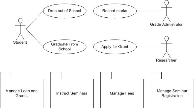
- Packages (optional). Packages are UML constructs that enable you to organize model elements (such as use cases) into groups. Packages are depicted as file folders and can be used on any of the UML diagrams, including both use case diagrams and class diagrams. I use packages only when my diagrams become unwieldy, which generally implies they cannot be printed on a single page, to organize a large diagram into smaller ones. Figure 3 depicts how Figure 1 could be reorganized with packages.
In the example depicted in Figure 1 students are enrolling in courses with the potential help of registrars. Professors input the marks students earn on assignments and registrars authorize the distribution of transcripts (report cards) to students. Note how for some use cases there is more than one actor involved. Moreover, note how some associations have arrowheads – any given use case association will have a zero or one arrowhead. The association between Student and Enroll in Seminar (in the version shown in Figure 4) indicates this use case is initially invoked by a student and not by a registrar (the Registrar actor is also involved with this use case). Understanding that associations don’t represent flows of information is important; they merely indicate an actor is somehow involved with a use case. Information is flowing back and forth between the actor and the use case, for example, students would need to indicate which seminars they want to enroll in and the system would need to indicate to the students whether they have been enrolled. However, use case diagrams don’t model this sort of information. Information flow can be modeled using UML activity diagrams. The line between the Enroll in Seminar use case and the Registrar actor has no arrowhead, indicating it is not clear how the interaction between the system and registrars start. Perhaps a registrar may notice a student needs help and offers assistance, whereas other times, the student may request help from the registrar, important information that would be documented in the description of the use case. Actors are always involved with at least one use case and are always drawn on the outside edges of a use case diagram.
Figure 1. System use case diagram.

Figure 2. Using System boundary boxes to indicate releases.
Creating Use Case Diagrams
I like to start by identifying as many actors as possible. You should ask how the actors interact with the system to identify an initial set of use cases. Then, on the diagram, you connect the actors with the use cases with which they are involved. If an actor supplies information, initiates the use case, or receives any information as a result of the use case, then there should be an association between them. I generally don’t include arrowheads on the association lines because my experience is that people confuse them for indications of information flow, not initial invocation. As I begin to notice similarities between use cases, or between actors, I start modeling the appropriate relationships between them (see the Reuse Opportunities section).
The preceding paragraph describes my general use case modeling style, an “actors first” approach. Others like to start by identifying one actor and the use cases that they’re involved with first and then evolve the model from there. Both approaches work. The important point is that different people take different approaches so you need to be flexible when you’re following AM’s practice of Model With Others.
Reuse in Use Case Diagrams
Figure 4 shows the three types of relationships between use cases — extends, includes, and inheritance — as well as inheritance between actors. I like to think of extend relationships as the equivalent of a “hardware interrupt” because you don’t know when or if the extending use case will be invoked (perhaps a better way to look at this is extending use cases are conditional). Include relationships as the equivalent of a procedure call. Inheritance is applied in the same way as you would on UML class diagrams — to model specialization of use cases or actors in this case. The essay Reuse in Use Case Models describes these relationships in greater detail.
Figure 4. Use case reuse.

Remaining Agile With Use Case Diagrams
So how can you keep use case modeling agile? First, focus on keeping it as simple as possible. Use simple, flexible tools to model with. I’ll typically create use case diagrams on a whiteboard, as you see in Figure 5 which is an example of an initial diagram that I would draw with my stakeholders. AM tells us that Content is More Important Than Representation so it isn’t a big issue that the diagram is hand drawn, it’s just barely good enough and that’s all that we need. It’s also perfectly okay that the diagram isn’t complete, there’s clearly more to a university than what is depicted, because we can always modify the diagram as we need to.
Figure 5. Whiteboard sketch.

In parallel to creating the sketch I would also write a very brief description of each use case, often on a whiteboard as well. The goal is to record just enough information about the use case so that we understand what it is all about. If we need more details we can always add them later either as an essential/business use case or a system use case.
Source
This artifact description is excerpted from Chapter 5 of The Object Primer 3rd Edition: Agile Model Driven Development with UML 2.
Translations
Disclaimer
The notation used in these diagrams, particularly the hand drawn ones, may not conform perfectly to the current version of the UML for one or more of reasons:
- The notation may have evolved from when I originally developed the diagrams. The UML evolves over time, and I may not have kept the diagrams up to date.
- I may have gotten it wrong in the first place. Although these diagrams were thoroughly reviewed for the book, and have been reviewed by thousands of people online since then, an error may have gotten past of us. We’re only human.
- I may have chosen to apply the notation in “non-standard” ways. An agile modeler is more interested in created models which communicate effectively than in conforming to notation rules set by a committee.
If you’re really concerned about the nuances of “official” UML notation then read the current version of the UML specification.