
UML Sequence Diagrams: An Agile Introduction
- Usage scenarios. A usage scenario is a description of a potential way your system is used. The logic of a usage scenario may be part of a use case, perhaps an alternate course. It may also be one entire pass through a use case, such as the logic described by the basic course of action or a portion of the basic course of action, plus one or more alternate scenarios. The logic of a usage scenario may also be a pass through the logic contained in several use cases. For example, a student enrolls in the university, and then immediately enrolls in three seminars.
- The logic of methods. Sequence diagrams can be used to explore the logic of a complex operation, function, or procedure. One way to think of sequence diagrams, particularly highly detailed diagrams, is as visual object code.
- The logic of services. A service is effectively a high-level method, often one that can be invoked by a wide variety of clients. This includes web-services as well as business transactions implemented by a variety of technologies such as CICS/COBOL or CORBA-compliant object request brokers (ORBs).
Let’s start with three simple examples. Figure 1 depicts a UML sequence diagram for the Enroll in University use case, taking a system-level approach where the interactions between the actors and the system are shown. Figure 2 depicts a sequence diagram for the detailed logic of a service to determine if an applicant is already a student at the university. The logic for how to enroll in a seminar is captured in Figure 3. I will often develop a system-level sequence diagram with my stakeholders to help to both visualize and validate the logic of a usage scenario. It also helps me to identify significant methods/services, such as checking to see if the applicant already exists as a student, which my system must support.
Figure 1. System-level sequence diagram.

The reason why they’re called sequence diagrams should be obvious: the sequential nature of the logic is shown via the ordering of the messages (the horizontal arrows). The first message starts in the top left corner, the next message appears just below that one, and so on.
Figure 2. Service-level sequence diagram.

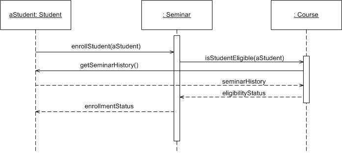
The boxes across the top of the diagram represent classifiers or their instances, typically use cases, objects, classes, or actors. Because you can send messages to both objects and classes, objects respond to messages through the invocation of an operation and classes do so through the invocation of static operations, it makes sense to include both on sequence diagrams. Because actors initiate and take an active part in usage scenarios, they can also be included in sequence diagrams. Objects have labels in the standard UML format name: ClassName , where “name”� is optional (objects that haven’t been given a name on the diagram are called anonymous objects). Classes have labels in the format ClassName, and actors have names in the format Actor Name . Notice how object labels are underlined, classes and actors are not. For example, in Figure 3, you see the Student object has the name aStudent, this is called a named object, whereas the instance of Seminar is an anonymous object. The instance of Student was given a name because it is used in several places as a parameter in messages, whereas the instance of the Seminar didn’t need to be referenced anywhere else in the diagram and thus could be anonymous. In Figure 2 the Student class sends messages to the PersistenceFramework class (which could have been given the stereotype <> but wasn’t to keep the diagram simple). Any message sent to a class is implemented as a static method, more on this later.
Figure 3. Enrolling in a seminar (method).
The dashed lines hanging from the boxes are called object lifelines, representing the life span of the object during the scenario being modeled. The long, thin boxes on the lifelines are activation boxes, also called method-invocation boxes, which indicate processing is being performed by the target object/class to fulfill a message. I will only draw activation boxes when I’m using a tool that natively supports them, such as a sophisticated CASE tool, and when I want to explore performance issues. Activation boxes are too awkward to draw on whiteboards or with simple drawing tools such that don’t easily support them.
The X at the bottom of an activation box, an example of which is presented in Figure 4, is a UML convention to indicate an object has been removed from memory. In languages such as C++ where you need to manage memory yourself you need to invoke an object’s destructor, typically modeled a message with the stereotype of <>. In languages such as Java or C# where memory is managed for you and objects that are no longer needed are automatically removed from memory, something often referred to as garbage collection, you do not need to model the message. I generally don’t bother with modeling object destruction at all and will instead trust that the programmers, often myself, will implement low-level details such as this appropriately.
Figure 4 presents a complex UML sequence diagram for the basic course of action for the Enroll in Seminar use case. This is an alternative way for modeling the logic of a usage scenario, instead of doing it at the system-level such as Figure 1 you simply dive straight into modeling the detailed logic at the object-level. I’ll take this approach when I’m working with developers who are experienced sequence diagrammers and I have a large working space (either a huge whiteboard or a CASE tool installed on a workstation with a very large screen and good graphic card). Most of the time I’ll draw system-level diagrams first and then create small diagrams along the lines of what is shown in Figures 2 and 3.
Figure 4. Basic course of action for the Enroll in Seminar use case.

Messages are indicated on UML sequence diagrams as labeled arrows, when the source and target of a message is an object or class the label is the signature of the method invoked in response to the message. However, if either the source or target is a human actor, then the message is labeled with brief text describing the information being communicated. For example, in Figure 4 the EnrollInSeminar object sends the message isEligibleToEnroll(theStudent) to the instance of Seminar. Notice how I include both the method’s name and the name of the parameters, if any, passed into it. The Student actor provides information to the SecurityLogon object via the messages labeled name and student number (these really aren’t messages, they are actually user interactions).
Return values are optionally indicated using a dashed arrow with a label indicating the return value. For example, the return value theStudent is indicated coming back from the Student class as the result of invoking a message, whereas no return value is indicated as the result of sending the message isEligibleToEnroll(theStudent) to Seminar. My style is not to indicate the return values when it’s obvious what is being returned, so I don’t clutter my sequence diagrams (as you can see, sequence diagrams get complicated fairly quickly). Figure 5shows an alternate way to indicate return values using the format message: returnValue for messages, as you can see with isEligibleToEnroll(theStudent): false.
Notice the use of stereotypes throughout the diagram. For the boxes, I applied the stereotypes <>, <>, and <> indicating they represent an actor, a controller class, or a user interface (UI) class, respectively. I’ve also used visual stereotypes on some diagrams – a stick figure for actors; the robustness diagram visual stereotypes for controller, interface, and entity objects; and a drum for the database. Stereotypes are also used on messages. Common practice on UML diagrams is to indicate creation and destruction messages with the stereotypes of <> and <>, respectively. For example, you see the SecurityLogon object is created in this manner (actually, this message would likely be sent to the class that would then result in a return value of the created object, so I cheated a bit). This object later destroys itself in a similar manner, presumably when the window is closed.
I used a UML note in Figure 4; notes are basically free-form text that can be placed on any UML diagram, to provide a header for the diagram ,indicating its title and identifier (as you may have noticed, I give unique identifiers to all artifacts that I intend to keep). Notes are depicted as a piece of paper with the top-right corner folded over. I also used a note to indicate future work that needs to be done, either during analysis or design, in this diagram-the qualifications() message likely represents a series of messages sent to the student object. Common UML practice is to anchor a note to another model element with a dashed line when appropriate, in this case the note is attached to the message.
Although Figure 4 models the logic of the basic course of action for the Enroll in Seminar use case how would you go about modeling alternate courses? The easiest way to do so is to create a single sequence diagram for each alternate course, as you see depicted in Figure 5. This diagram models only the logic of the alternate course, as you can tell by the numbering of the steps on the left-hand side of the diagram, and the header note for the diagram indicates it is an alternate course of action. Also notice how the ID of this diagram includes that this is alternate course C, yet another modeling rule of thumb I have found useful over the years.
Figure 5. An alternate course of action for the Enroll in Seminar use case.

Let’s consider other sequence diagramming notation. Figure 5 includes an initial message, Student chooses seminar, which is indicated by the filled in circle. This could easily have been indicated via a method invocation, perhaps enrollIn(seminar). Figure 6 shows another way to indicate object creation – sending the new message to a class. We’ve actually seen three ways to achieve this, the other two being to send a message with the <> stereotype and/or to send a message into the side of the classifier symbol (for example in Figure 4 the message going into the side of EnrollInSeminar or in Figure 6 the message going into the side of StudentInfoPage. My advice is to choose one style and stick to it.
Figures 6 and 7 each depict a way to indicate looping logic. One way is to show a frame with the label loop and a constraint indicating what is being looped through, such as for each seminar in Figure 6. Another approach is to simply precede a message that will be invoked several times with an asterisk, as you see in Figure 7 with the inclusion of the Enroll in Seminar use case.
Figure 6. Outputting transcripts.
![]()
Figure 6 includes an asynchronous message, the message to the system printer which has the partial arrowhead. An asynchronous message is one where the sender doesn’t wait for the result of the message, instead it processes the result when and if it ever comes back. Up until this point all other messages have been synchronous, messages where the sender waits for the result before continuing on. It is common to send asynchronous messages to hardware devices or autonomous software services such as message buses.
The method of modeling the inclusion of use cases using in Figure 7 is something that I first proposed in The Elements of UML Style although I have no doubt that others use this approach as well. I basically show the use case as a bubble across the top of the diagram, just like any other classifier, and show a message sent to it with the <> stereotype. This is consistent with both use case diagramming and sequence diagramming practices.
Figure 7. Enrolling in the University.
Figure 7 is also interesting because it shows how to model conditional logic. In this case a frame with the label alt is used along with a guard, in this case applicant on eligibility list. The frame is separated into regions separated by dashed lines. In this case there are two regions, one for each alternative, although you can have as many regions as you require (to support the visual equivalent of a case statement). Each region requires a guard.
Visual Coding With Sequence Diagrams
Earlier I stated that sequence diagrams are effectively a form of visual coding, or perhaps another way to think of it is that sequence diagrams can be used for very detailed design. When I developed the sequence diagram of Figure 4 I made several decisions that could potentially affect my other models. For example, as I modeled Step 10, I made the design decision that the fee display screen also handled the verification by the student that the fees were acceptable.
Also, as I was modeling Steps 2 and 3, I came to the realization that students should probably have passwords to get into the system. When you’re following the AM practices of Active Stakeholder Participation and Model With Others it’s easy to find out if ideas such as this make sense because all you need to do is ask. In this case I discovered I was wrong: the combination of name and student number is unique enough for our purposes and the university didn’t want the added complexity of password management. This is an interesting decision that would potentially be recorded as a business rule because it is an operating policy of the university, indicating the need to follow the practice Iterate To Another Artifact and jot down the rule if we’re interested in keeping a permanent record of it.
How to Draw Sequence Diagrams
I’ve been trying to explain to people how to draw sequence diagrams for years, and what I’ve discovered is that the people who get it are either very good at thinking in a logical manner and/or they are good at writing software code. Sequence diagramming really is visual coding, even when you are modeling a usage scenario via a system-level sequence diagram.
When I’m creating a sequence diagram I’ll start by identifying the scope of what I’m trying to model, and because I prefer to follow the AM practice Model in Small Increments I’ll typically tackle small usage scenarios at the system level or a single method/service at the detailed object level. A diagram such as Figure 4 is too complex to be useful in my experience.
I’ll then work through the logic with at least one more person, laying out classifiers across the top as I need them. I automatically add the object lifelines but as I indicated earlier will typically not invest time adding activation boxes. The heart of the diagram is in the messages, which I add to the diagram one at a time as I work through the logic. I rarely indicate return values, instead I’ll give messages intelligent names which often make it clear what is being returned.
It is interesting to note that as you sequence diagram you will identify new responsibilities for classes and objects, and, sometimes, even new classes. The implication is that you may want to update your class model appropriately, agile modelers will follow the practice Create Several Models in Parallel, something that CASE tools will do automatically. Remember, each message sent to a class invokes a static method/operation on that class each message sent to an object invokes an operation on that object.
Regarding style issues for sequence diagramming, I prefer to draw messages going from left-to-right and return values from right-to-left. Unfortunately, that doesn’t always work with complex objects/classes. I justify the label on messages and return vlues, so they are closest to the arrowhead. Layering the sequence diagrams, from left-to-right, increases consistency and thus readability. Also, I indicate the actors, then the controller class(es), and then the user interface class(es), and, finally, the business class(es). During design, you probably need to add system and persistence classes, which I usually put on the right-most side of sequence diagrams. Laying your sequence diagrams in this manner often makes them easier to read and also makes it easier to find layering logic problems, such as user interface classes directly accessing persistence classes.
Keeping it Agile
The most important things that you can do is to keep your diagrams simple, both content wise and tool wise. I will sketch sequence diagrams on whiteboards to think something through, either to verify the logic in a use case or to design a method or service. I rarely keep sequence diagrams as I find their true value is in their creation.
A common mistake is to try to create a complete set of sequence diagrams for your system. I’ve seen teams waste months creating several sequence diagrams for each of their use cases, one for the basic course of action and one for each alternate course. My advice is to only create a sequence diagram when you have complex logic that you want to think through – if the logic is straightforward the sequence diagram won’t add any value, you had might as well go straight to code.
Source
This artifact description is excerpted from Chapter 11 of The Object Primer 3rd Edition: Agile Model Driven Development with UML 2.
Disclaimer
The notation used in these diagrams, particularly the hand drawn ones, may not conform perfectly to the current version of the UML for one or more of reasons:
- The notation may have evolved from when I originally developed the diagrams. The UML evolves over time, and I may not have kept the diagrams up to date.
- I may have gotten it wrong in the first place. Although these diagrams were thoroughly reviewed for the book, and have been reviewed by thousands of people online since then, an error may have gotten past of us. We’re only human.
- I may have chosen to apply the notation in “non-standard” ways. An agile modeler is more interested in created models which communicate effectively than in conforming to notation rules set by a committee.
- It likely doesn’t matter anyway, because the modeling tool(s) that you’re using likely won’t fully support the current version of the UML notation perfectly anyway. Bottom line is that you’re going to be constrained by your tools anyway.
If you’re really concerned about the nuances of “official” UML notation then read the current version of the UML specification.